Although most mechanics and automotive machinists understand what the individual areas of a crankshaft are called, most vehicle owners do not. Because of this, it is important for those seeking repair services to learn the terminology used by automotive professionals and gain the ability to identify these terms with the areas on their crankshaft.
In the diagrams below you will find coded arrows that point to specific areas on the crankshaft. The arrows are identified by industry standard terminology used to describe the area being viewed. A brief but concise description of what this area is responsible for is available below the crankshaft diagrams.
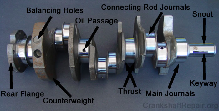
 Balancing Holes
When the crankshaft rotates, at high RPMs, vibration can occur. Balancing the crankshaft, which requires that weight is either removed or added to the crankshaft, is often accomplished with the pictured balancing holes.
Connecting Rod Journals (Pins)
The connecting rod journals, often referred to as pins, are where the connecting rods are attached to with bearings. To maintain adequate timing, the connecting rod journals maintain a specific degree apart from each other, which does vary for specific engines and ignition firing orders.
Counterweights
Counterweights, as their name implies, adds weight to the crankshaft so that it reduces vibration at any RPM or position. Counterweights help to offset the weight from connecting rods and pistons.
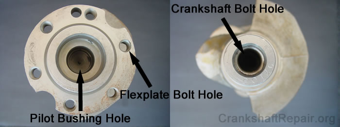
Crankshaft Bolt Hole (Balancer Bolt Hole)
The crankshaft bolt, or as is commonly referred to as a balancer bolt, is used to secure the harmonic balancer (damper) to the crankshaft. The balancer bolt hole is located on the snout of the crankshaft and is typically torqued to 150 ft lbs or greater on many crankshafts.
Flywheel/Flexplate Bolt Holes
A flywheel or flexplate contains a ring gear which a vehicle’s starter turns when the ignition is turned into the starting position. Manual transmissions use the flywheel surface to engage the clutch so that the vehicle will move. Regardless of what type of transmission your vehicle has, these bolt holes are used to secure either the flexplate or flywheel to the crankshaft.
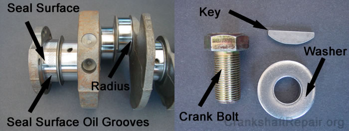
Key
The crankshaft key, which fits into the keyway as a press fit, is an important part of the crankshaft as it helps to align the harmonic balancer in the proper position. In addition to the properly locating the harmonic balancer, the key is also an important engine timing reference point.
Keyway
The keyway is machined into the crankshaft snout and accepts a special key to help align the crankshaft timing gear sprocket and harmonic balancer in a precise location.
Main Journals
Each main journal of a crankshaft runs in line with each other. This is the portion of the crankshaft that bolts into the engine block by main caps, with bearings installed, and must run true.
Oil Passages
Oil passages on the connecting rod and main journals help to feed oil directly to the bearings. The thin film of oil that forms between the bearings and the journals is what protects the crankshaft from damage.
Pilot Bearing or Bushing Hole
Manual transmissions utilize an input shaft that aids in the alignment of the clutch assembly to the flywheel. The input shaft alignment is made possible with the use of a pilot bearing or bushing, which is normally a pressed fit into the hole on the crankshaft’s rear flange. Because manual transmissions use a torque converter to connect the flexplate to the transmission, the use of a pilot bearing or bushing is not necessary, although some crankshafts have these installed from the factory even though they are not used.
Radius or Rolled Fillet
On each journal, where the bearing surface meets the counterweight, there is a radius or rolled fillet. Although small and typically measured with a radius gauge, this area adds a great deal of strength to the crankshaft. By minimizing 90 degree angles on each journal, the force of the combustion process is evenly distributed throughout the crankshaft.
Rear Flange
The rear flange of the crankshaft provides a strong surface area to accept the flexplate or flywheel bolts. The rear flange is often machined to help in balancing crankshafts as well.
Seal Surface
The seal surface on a crankshaft is responsible for helping to keep oil within the engine. The rear main seal is installed in the last main cap and gently rides over the seal surface to eliminate any voids where oil may exit the crankcase.
Seal Surface Oil Grooves
Especially on those engines which use rear main seals made of rope, the directional grooves help to redirect oil away from the seal as the crankshaft rotates. Many crankshafts do not have these grooves as they use a more efficient rubber seal.
Snout (Nose)
The crankshaft snout, or nose as many people refer to it as, provides a location for the crankshaft timing gear sprocket and harmonic balancer to attach to. The crankshaft snout contains a keyway and key so that the sprocket and balancer may be accurately positioned to ensure proper timing and balance.
Thrust
Every crankshaft installed must have a minute amount of clearance between the journals and bearings for oil. A crankshaft must also have a limited amount of backward and forward motion, which is commonly referred to as endplay. Most crankshafts are installed with .005-.010” of endplay, and the thrust surface of the crankshaft is what prohibits excessive endplay.
It is our hope that the diagram and terms noted above will better help you understand your crankshaft and the various parts that are often referred to as being in need of repair. If you found this information helpful, please consider rating this page below.
 (No Ratings Yet)
![]() Loading...
Loading...